Part 1: Setting up a new project
Creating a new project
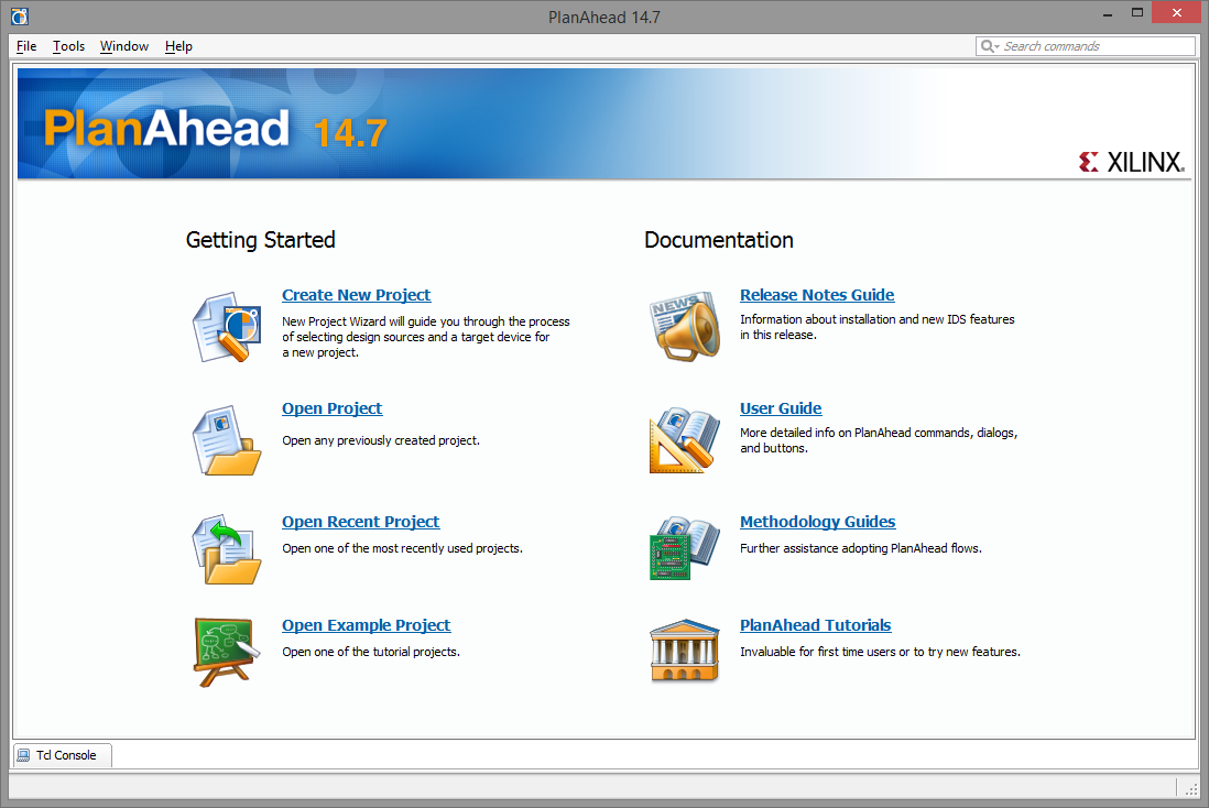
After starting PlanAhead, you will be greeted by the welcome screen. Select Create New Project.
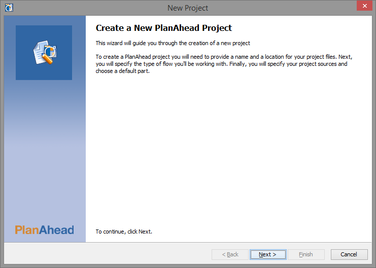
On the New Project wizard welcome page, click Next.
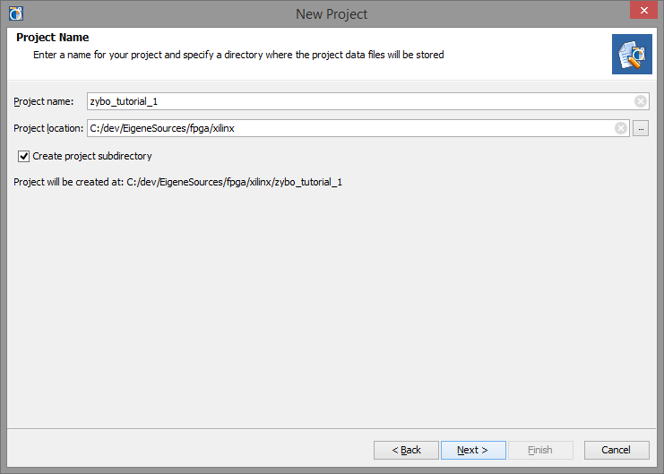
Now we define a name and location for the project — I'll use zybo_tutorial_1 — and then click Next to continue.
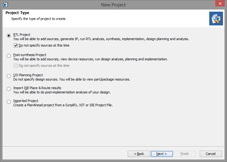
Since we create a project from ground up, select RTL Project and click Next.
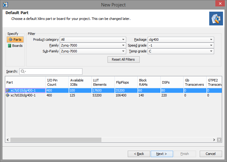
Now we get to select the board. ZedBoard users may find their board in the Boards tab. ZYBO users will have to select the chip at the time being. From looking at the board we can see that this is a Zynq-7000 series commercial grade CLG400 chip, with speed grade -1. Using the filters we'll eventually find the xc7z010clg400-1 part, which is the Zynq-7010 on the ZYBO. Select it and click Next.
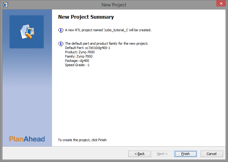
On the summary screen we confirm the selection and click Finish to be taken to the Project Manager.
Creating the embedded project
The Project Manager is part of the main screen of PlanAhead and shows the current target as well as project settings. It also presents shortcuts to the common steps in the workflow on the left, in the Flow Navigator.
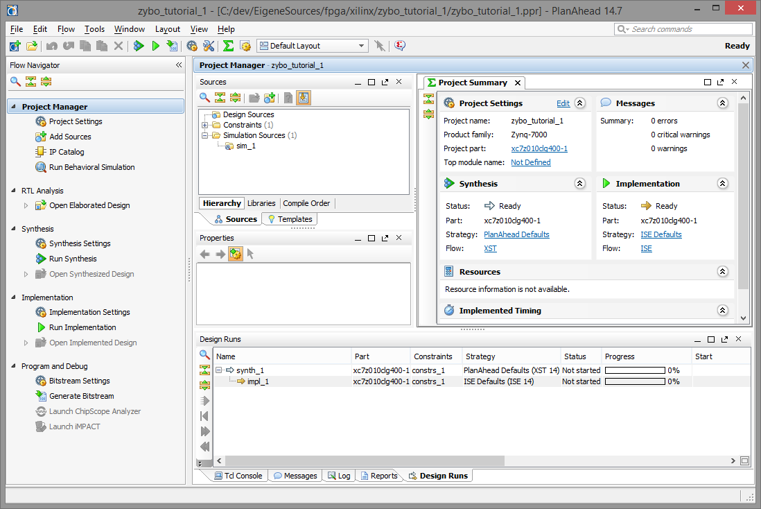
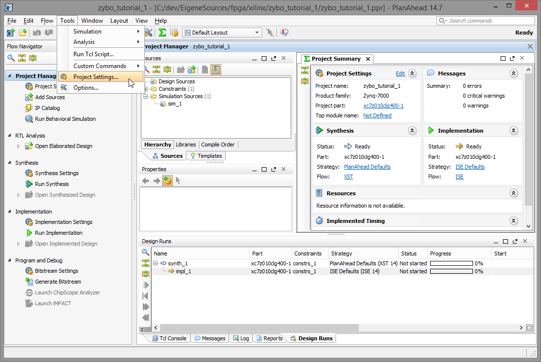
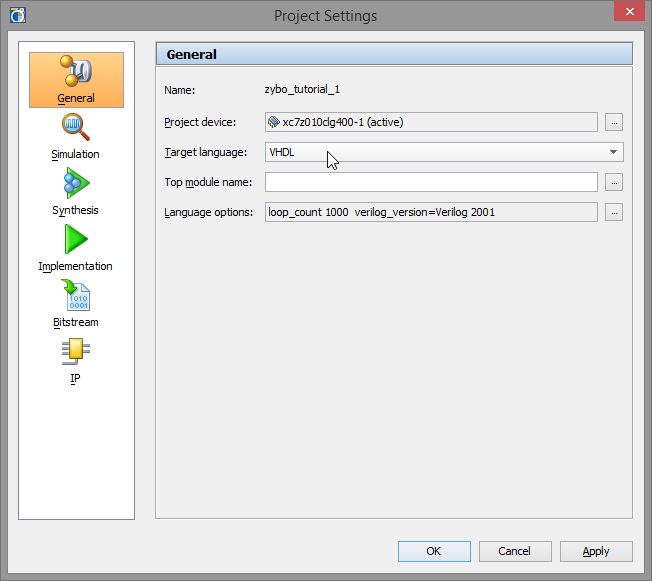
Before we can begin, we will verify the HDL language settings in the Tools, Project Settings menu.
Make sure that the Target language is set to either Verilog or VHDL, whichever you prefer. In this tutorial I will assume you selected VHDL here. Click OK to continue.
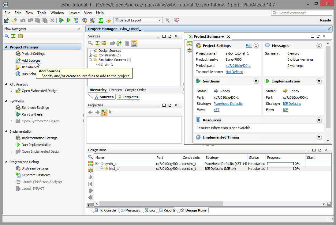
Next we will add some sources to the project. Select Add Sources in the Project Manager tab of the Flow Navigator on the left..
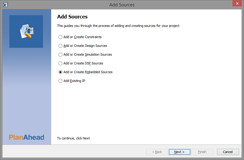
Select Add or Create Embedded Sources and click Next to continue.
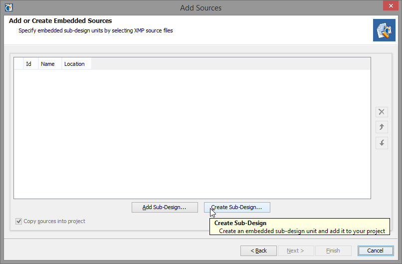
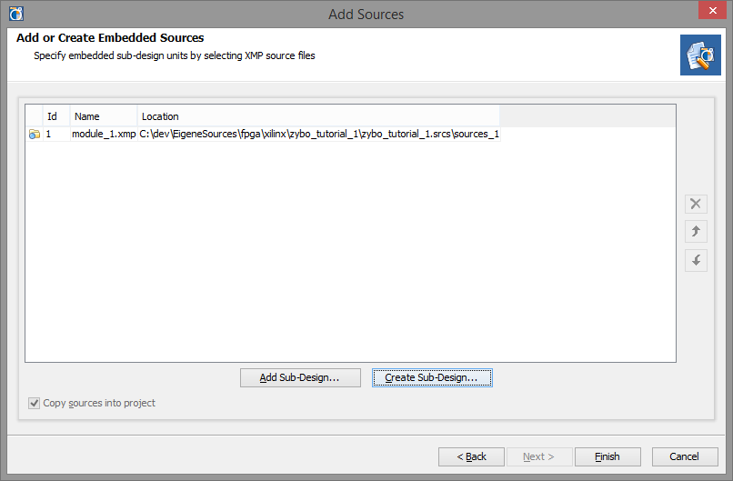
On the following screen, click Create Sub-Design.
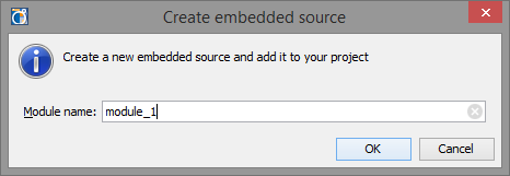
Enter the name of the new module. I'll use the default, module-1 here.
You will find the new module and its location in the list. Click Finish to be taken to Xilinx Platform Studio (XPS).
Preparing the board
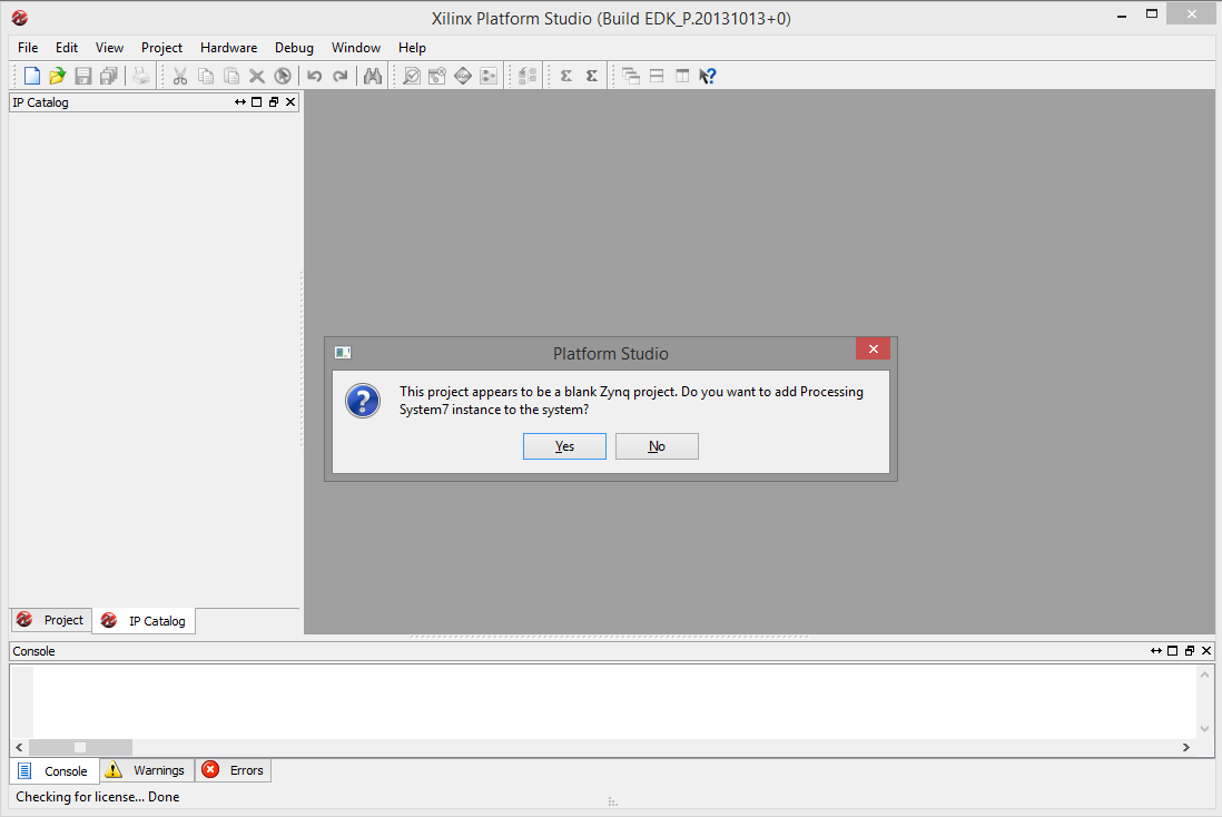
After XPS has opened, you'll be asked to add a new Processing System7 instance to the otherwise empty board. Confirm to do so by clicking Yes.
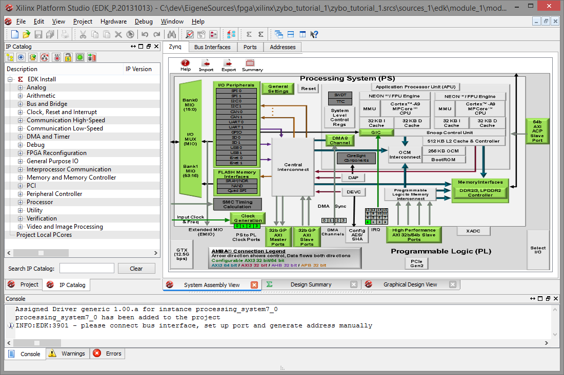
You will be presented with the Zynq tab of the System Assembly View. This is the place to configure the Zynq peripherals like the interrupt and memory controllers, clock generators etc. We won't use any of that in this tutorial.
Within the Zynq tab, click the Import button to import a board description.
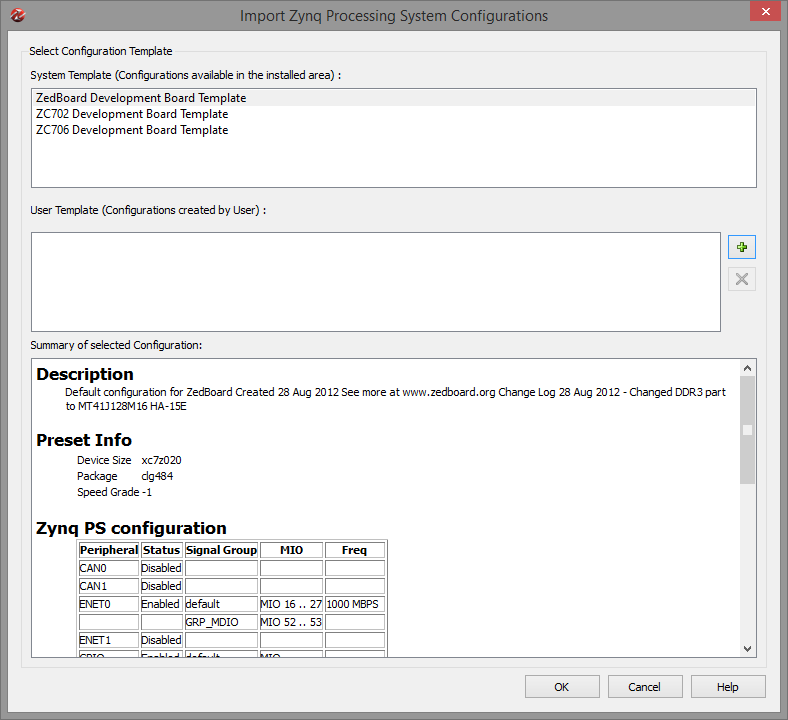
ZedBoard users may select the ZedBoard template here. There is no default template for the ZYBO at the moment, but we can download a ZYBO Board Definition (ZYBO_def.zip) file from the Digilent ZYBO product page. Click the + button to and add the definition XML file.
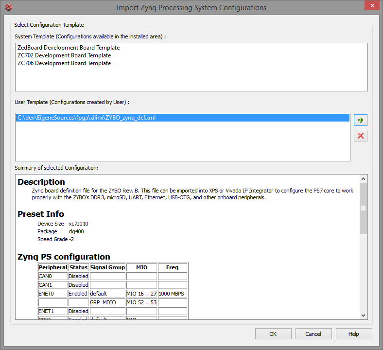
After adding a user template — in this case, the ZYBO_zynq_def.xml provided by Digilent — we can select it in the list. Click OK to continue.
Confirm that we want to overwrite any existing settings by clicking Yes.

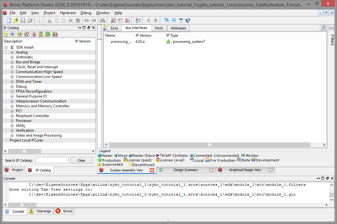
Nothing visible will have changed in the System Assembly View. Click the Bus Interface tab to see that we indeed have an empty board with only a Processing System7 instance added to it.
Creating a peripheral
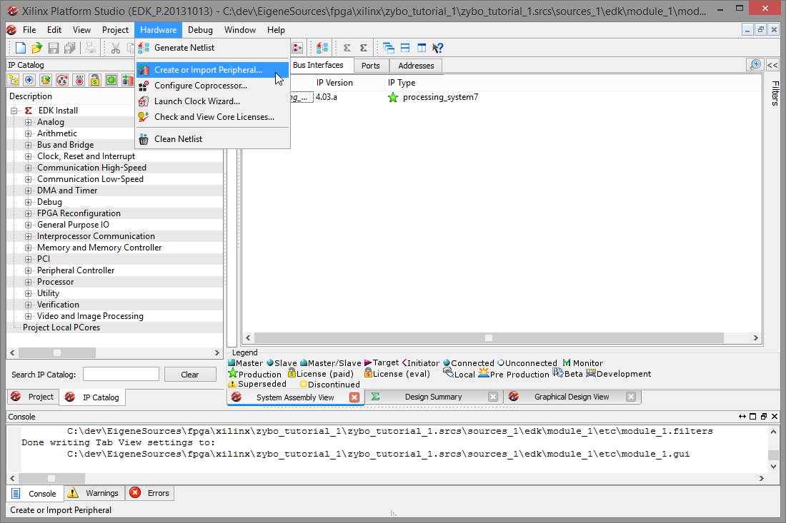
In order to create a new peripheral, select Hardware, Create or Import Peripheral to be taken to the next wizard.
On the welcome screen, click Next.
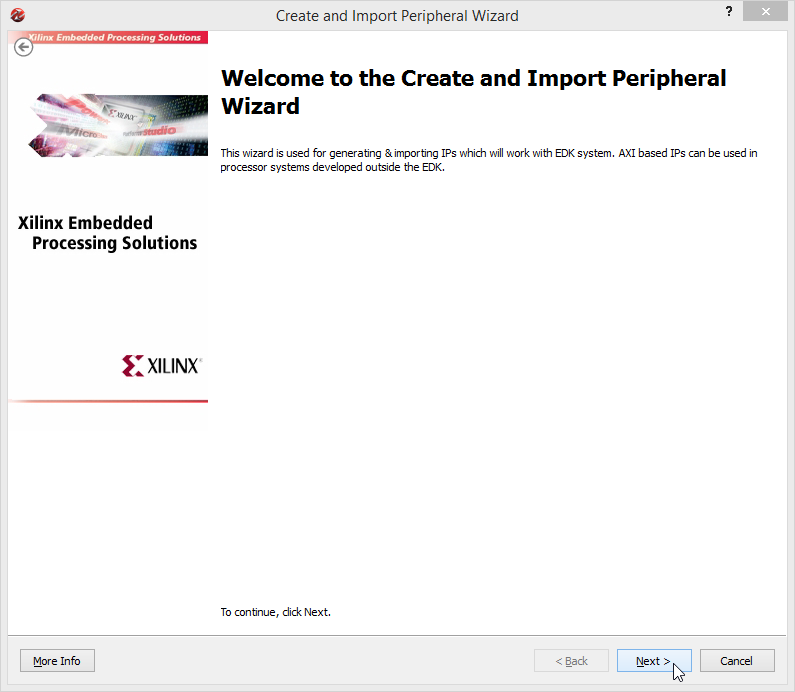
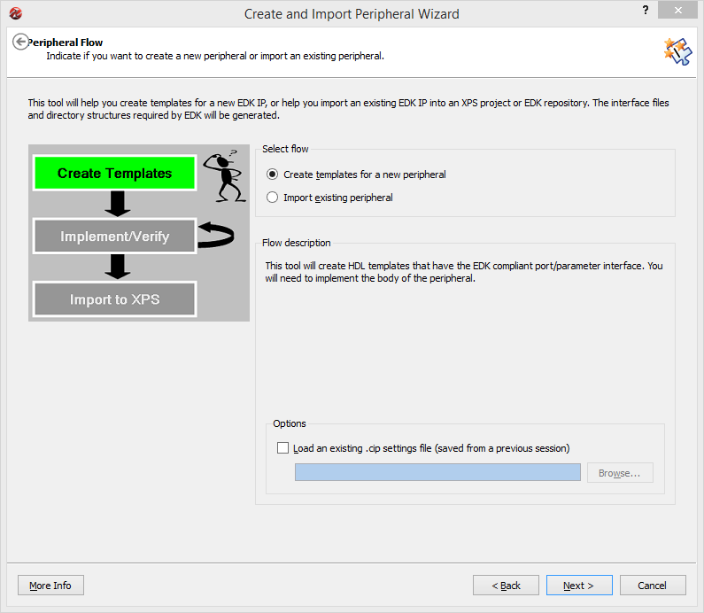
Notice the design flow on the left and select Create templates for a new peripheral. Click Next to continue.
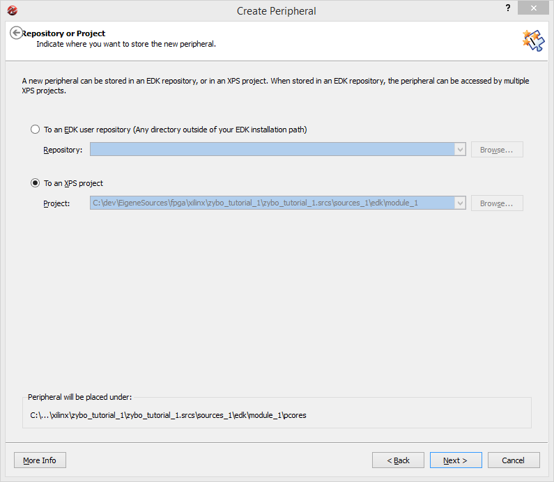
Select To an XPS project in order to create the peripheral locally, then click Next.
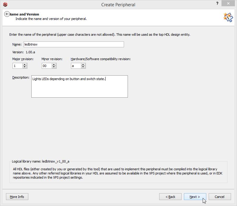
Enter a name, version and optionally a description. In this tutorial, I'll use ledbtnsw with the default values. Note that the description field only accepts ASCII and no fancy UTF8 characters. Click Next.
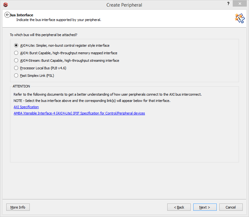
On the Bus Interface screen, the preferred bus connection can be selected. In case of the Zynq, AXI4 is the way to go. Since for this tutorial we do not need the bus at all, we'll simply select the tiniest variant, which is AXI4-Light and then click Next to continue.
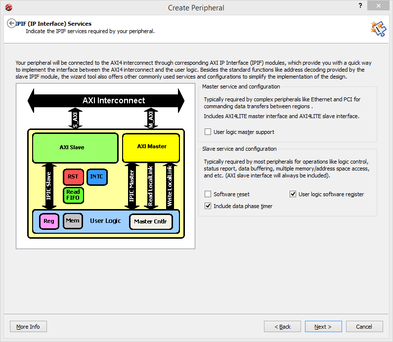
Change nothing on the IPIF Services screen, and click Next to continue. This way we get to have some software accessible registers which we don't need for this tutorial, but this allows for easy extension of the project afterwards.
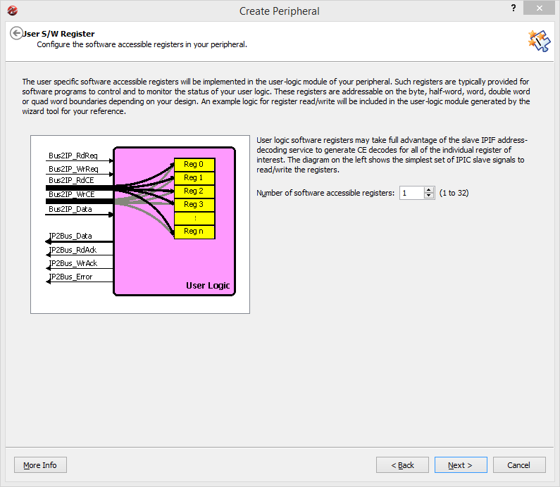
Select any amount of software accessible registers here if you plan on playing with them afterwards. We don't need them for this tutorial, so I'll selected 1. Use a larger number to see how address decoding works later in the HDL code. Then click Next.
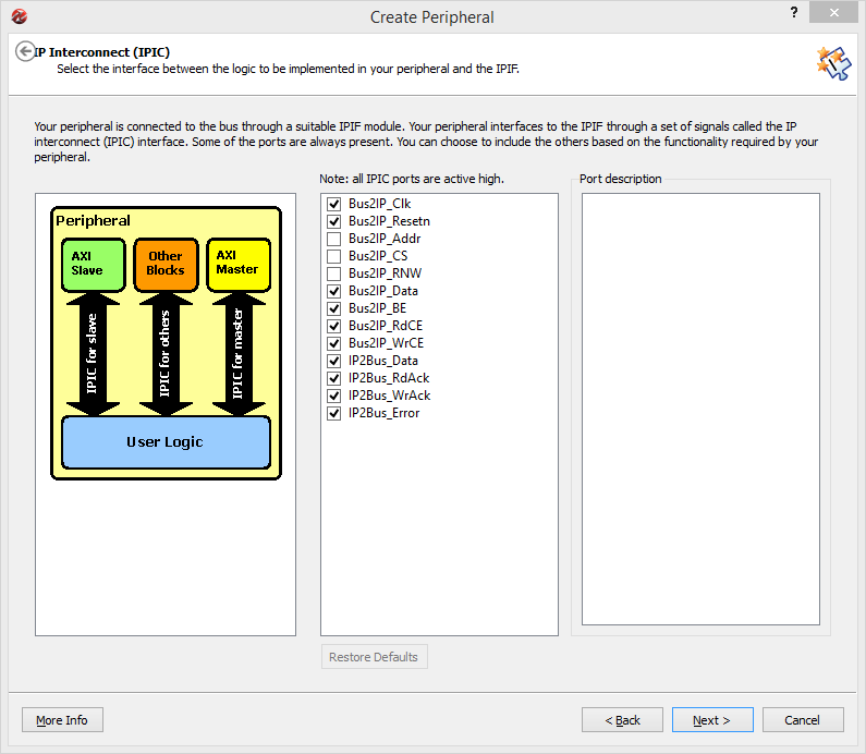
On the IP Interconnect screen nothing needs to be changed, so click Next to get rid of it.
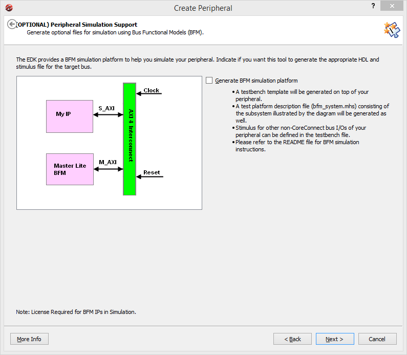
The Peripheral Simulation Support screen allows for the addition of Bus Functional Modeling support for the simulator. We don't need that for this tutorial, so click Next.
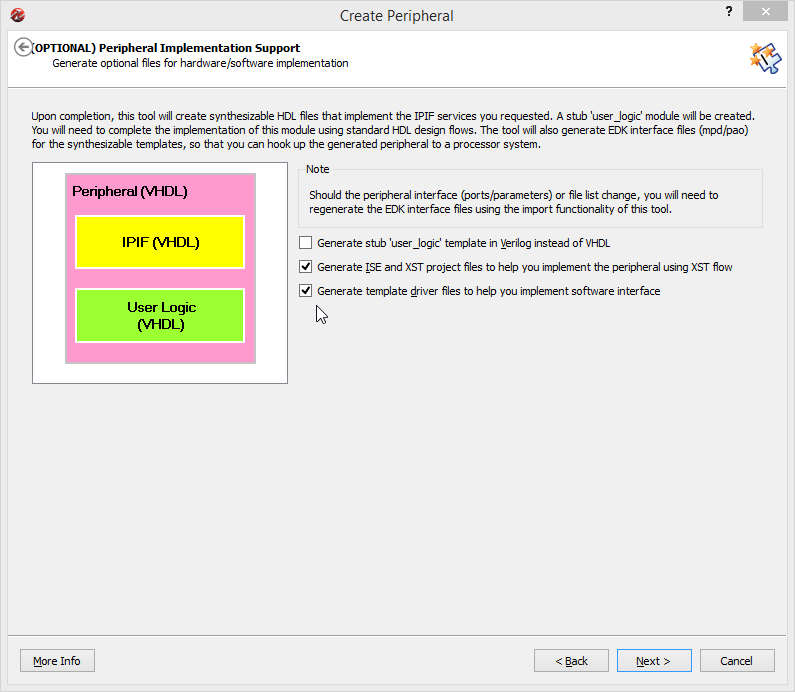
In the Peripheral Implementation Support screen, be select Generate ISE and XST project files and Generate template driver files. Only check the Verilog option if you plan on using that instead of VHDL. Click Next to arrive at the finish line.
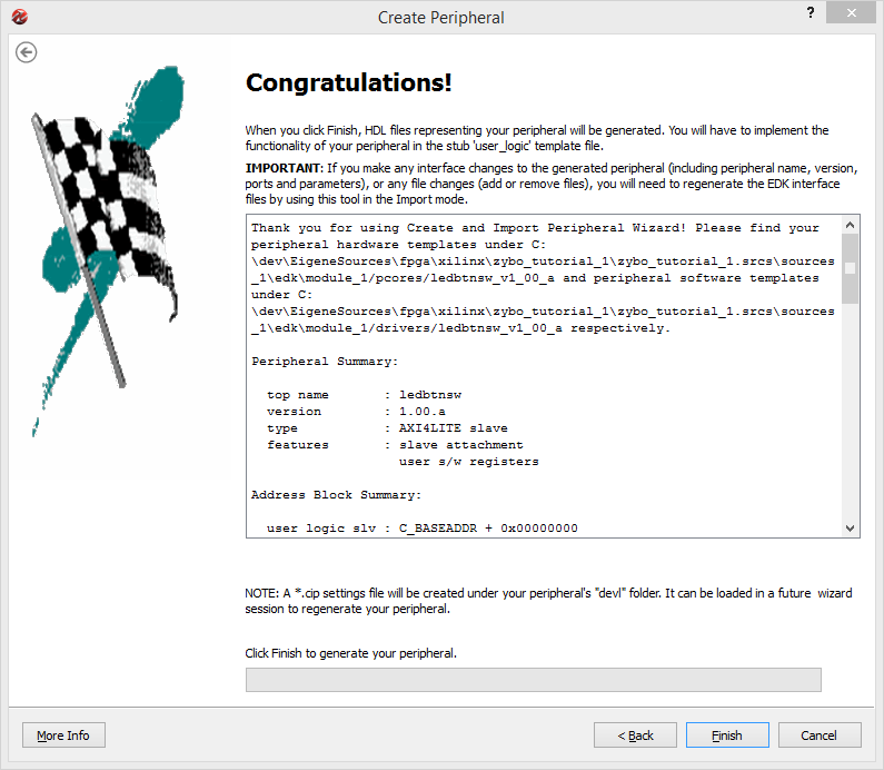
On the last screen, simply click Finish and wait for the wizard to complete.
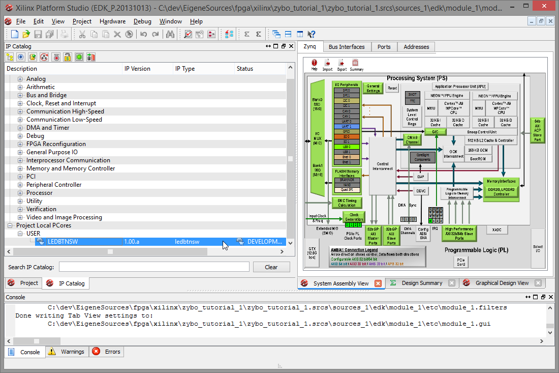
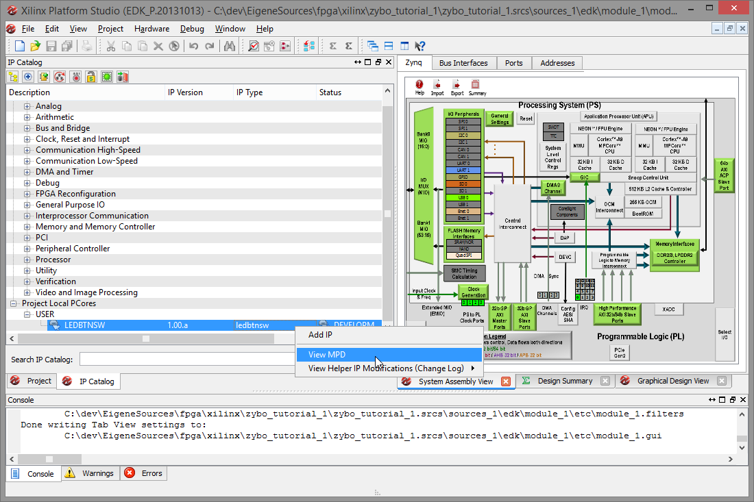
Back in XPS, you'll find the IP Catalog on the left. Scroll down and open the Project Local PCores and USER tree to find the new IP. Note that it is currently marked as DEVELOPMENT, meaning that any run of the synthesis tool later on will also synthesize this IP.
Right-click on the entry and select View MPD to open the Microprocessor Peripheral Description file.
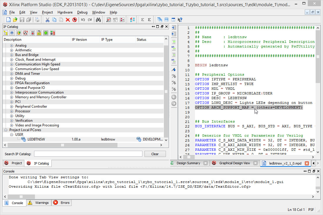
Take note of the ARCH_SUPPORT_MAP line; you will need re-add it later on.
Adding the peripheral
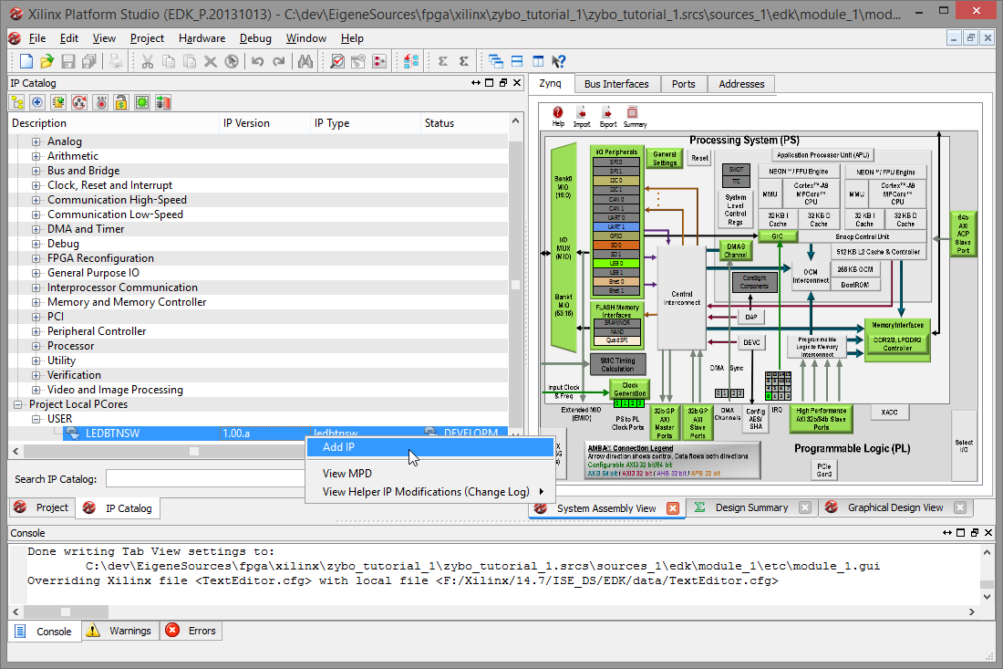
Right-click the IP again and slect Add IP to add it to the design.
Confirm the action by clicking Yes.

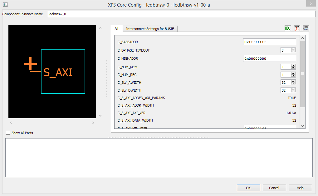
On the XPS Core Config window, you can review all generics/parameters setting for the IP. Simply click OK to continue.
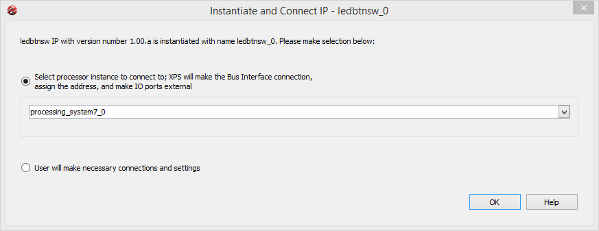
XPS detects that our IP contains a bus interface and will help us connecting it. Select the processing_system_7_0 instance and click OK to continue.
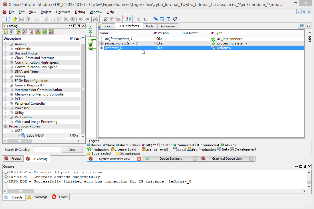
In the Bus Interfaces tab we can now confirm that a single instance of our IP has been added to the design and is connected to the processing system as an AXI slave.
We will now edit the created IP. Leave XPS open for the moment since we will need it again later on.
Parts of the tutorial
- Previous: Index.
- Next: Editing the IP logic.