Part 3: Peripheral import and ports configuration
Re-importing the peripheral
Head back to XPS. (If you accidentally closed it in the meantime, you can open it again from PlanAhead by double-clicking on the your-module.xmp file in the Sources pane.)
In XPS, select Hardware, Create or Import Peripheral again. Click Next.
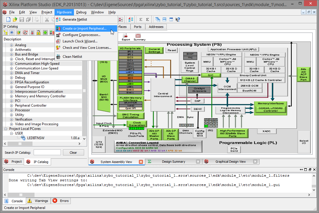
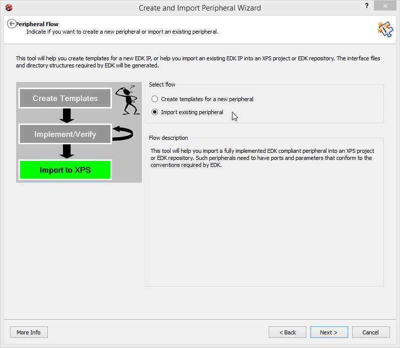
This time, we chose Import existing peripheral and Next.
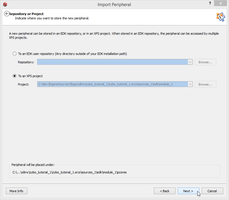
Like before, select To an XPS project, then click Next.
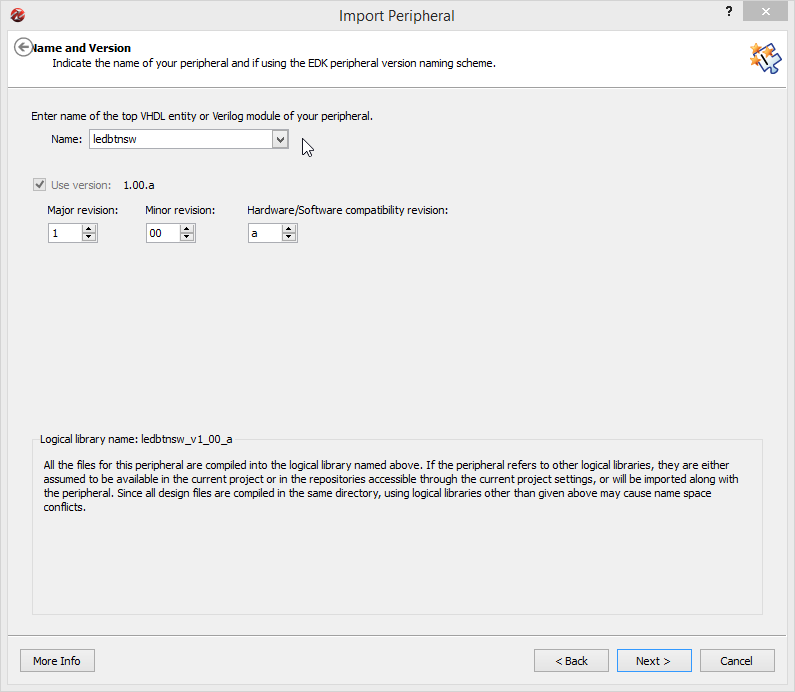
Select the IP we just edited and click Next.
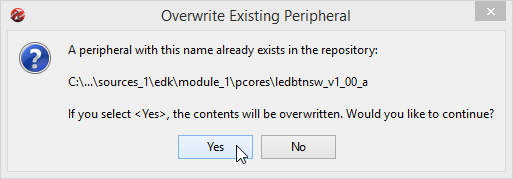
Confirm that we want to overwrite the local design with the changed IP description by clicking Yes.
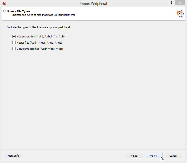
Check HDL sources files and click Next.
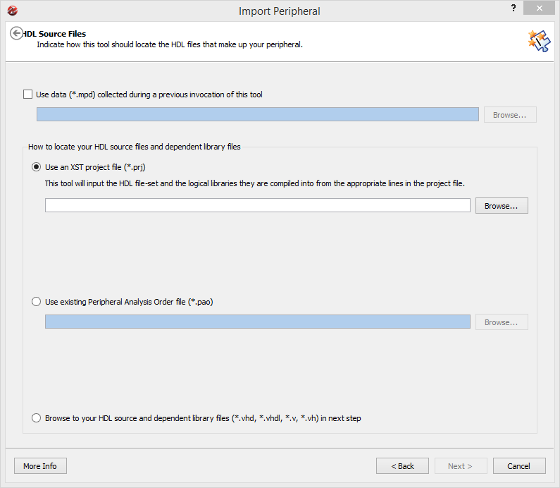
After that we are presented with two ways to select the HDL source files. If you are not able to import the files from ISE (option 1), select the PAO approach (option 2).
Option 1: Importing the XST project file
Select Use an XST project file and click Browse.
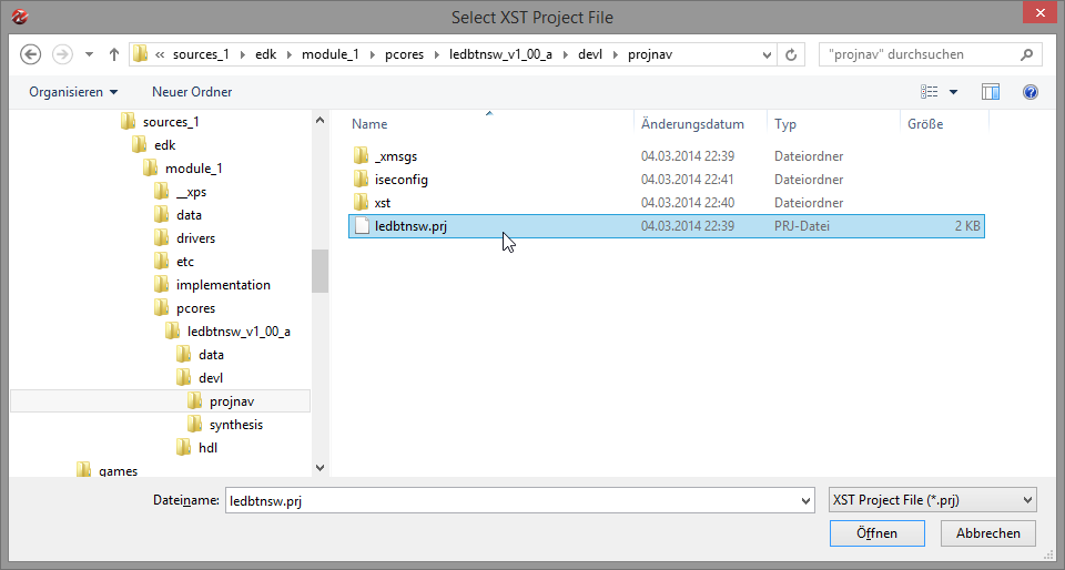
Navigate to the IP's devl/projnav directory and open the your-ip.prj from there.
Click Next on the import dialog and confirm that these files are to be imported by clicking Next again.
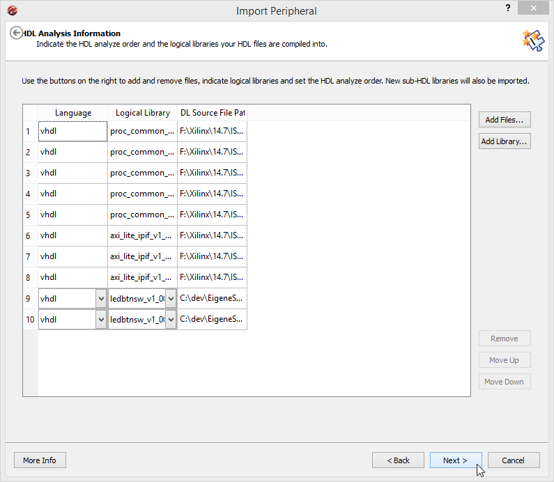
If everything works, you will be taken to to the Bus Interfaces dialog. It is possible that the import fails due to errors in your VHDL description. Head back to ISE and fix the error then. Another problem may be that the project file is in a format the importer does not like. This seems to happen sometimes; In this case, simply go back and use option 2, the PAO approach.
Option 2: Importing the PAO project file
Alternatively if the list of files used has not changed (i.e. like in this case where we only added logic to existing files), we can import an PAO file by selecting Use existing Peripheral Analysis Order file and clicking Browse.
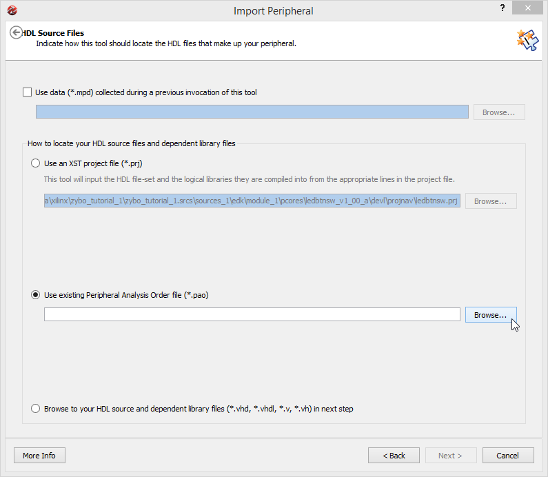
Select the PAO file in the data directory of the IP.
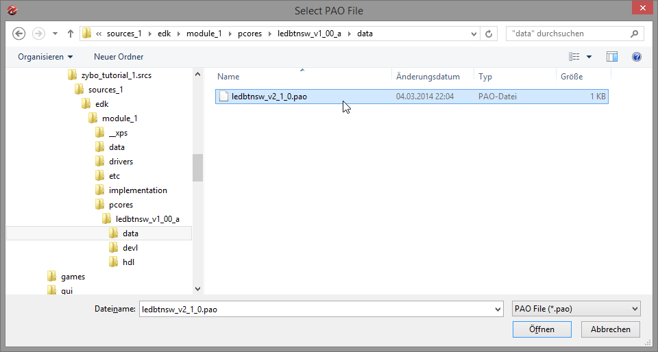
Click Next to import.
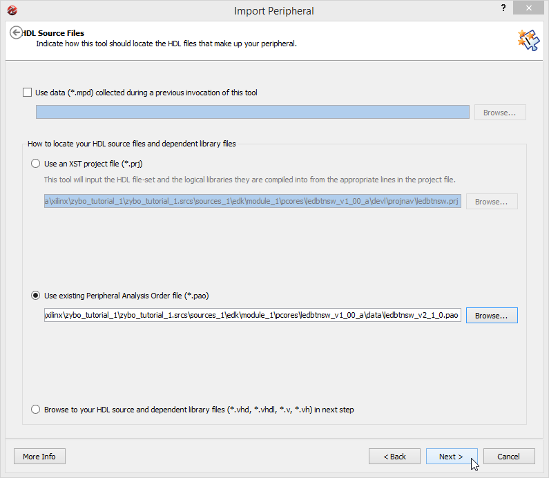
The list of files is a bit shorter than with the XST approach. Click Next to accept.
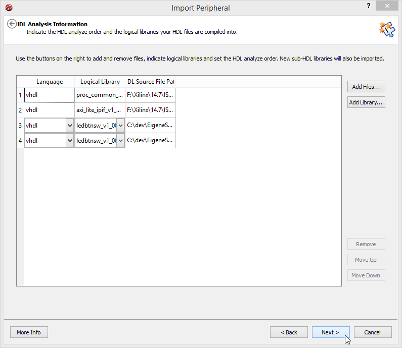
Again, if everything works we will be taken to the Bus Interfaces dialog.
IP Configuration
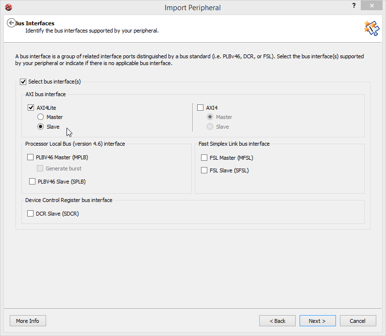
Since we created an AXI4-Lite peripheral with only Slave functionality, we will select that and confirm using Next.
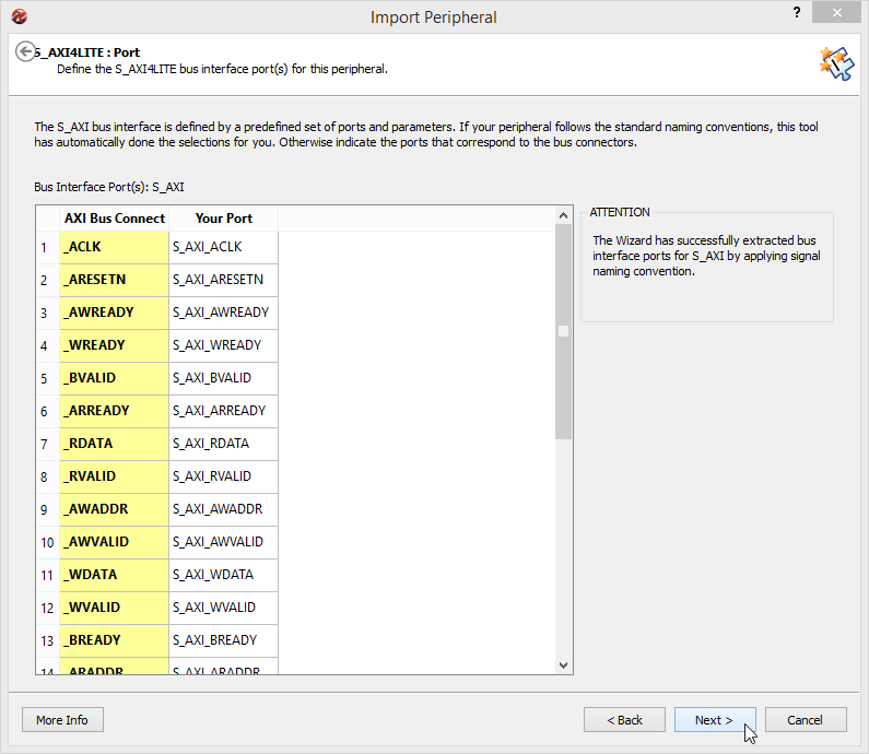
On the AXI4LITE Port screen nothing needs to be changed, so simply ignore it by clicking Next.
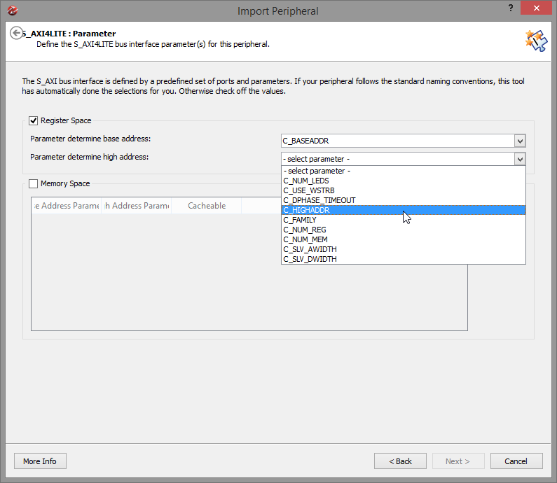
At the AXI4LITE Parameter screen we need to select the value for the Parameter determine high address field. Select the S_HIGHADDR generic from the dropdown list and continue using Next.
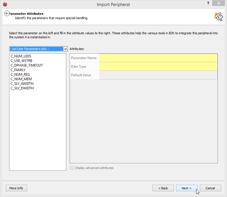
On the Parameter Attributes screen we could change our generics, but since we already set a reasonable default in the VHDL file, we can simply skip this window by selecting Next.
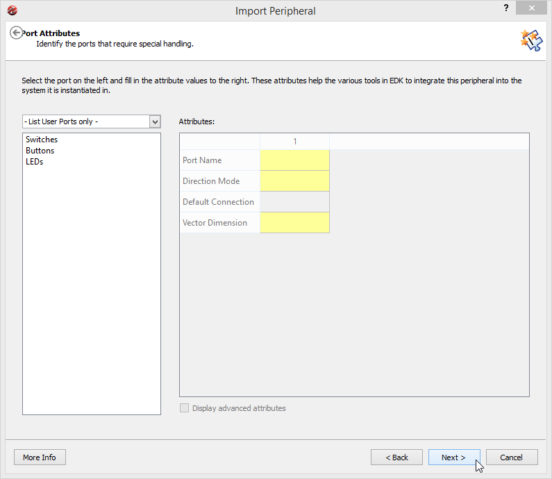
Next we can check our ports attributes (i.e. the direction mode, the name, default values etc.). Note that this dialog has a bug as per ISE Suite 14.7 preventing the displayed parameters to change once a value is selected. This does not affect the IP itself, so you can safely ignore it.
Click Next to continue.
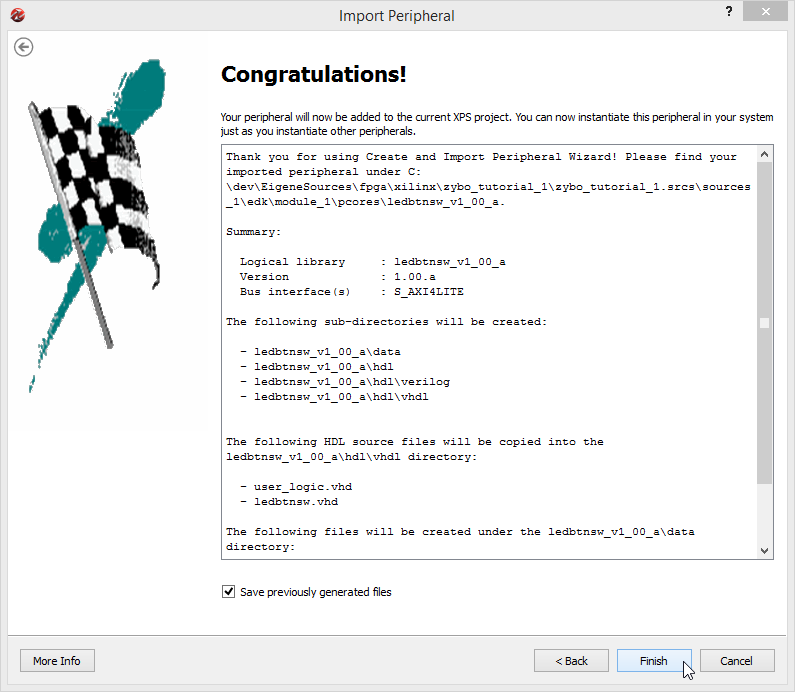
On the final dialog window, select Finish and wait.
Update IP status
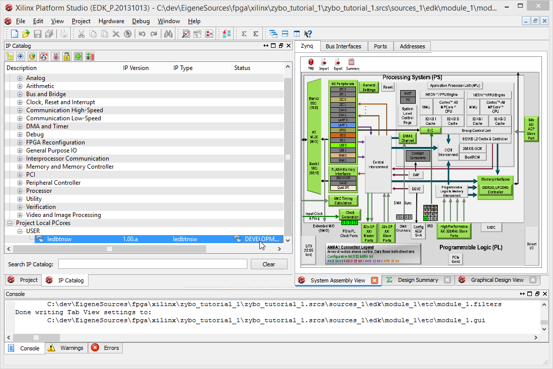
Looking at the IP Catalog you will notice that the currently imported IP is now marked as PRODUCTION. In that status, the IP will only be synthesized once (i.e. a first time) and
wont ever update again, no matter how many changes you apply to the sources files. In order to continue developing on it, we'll need to change it back to DEVELOPMENT.
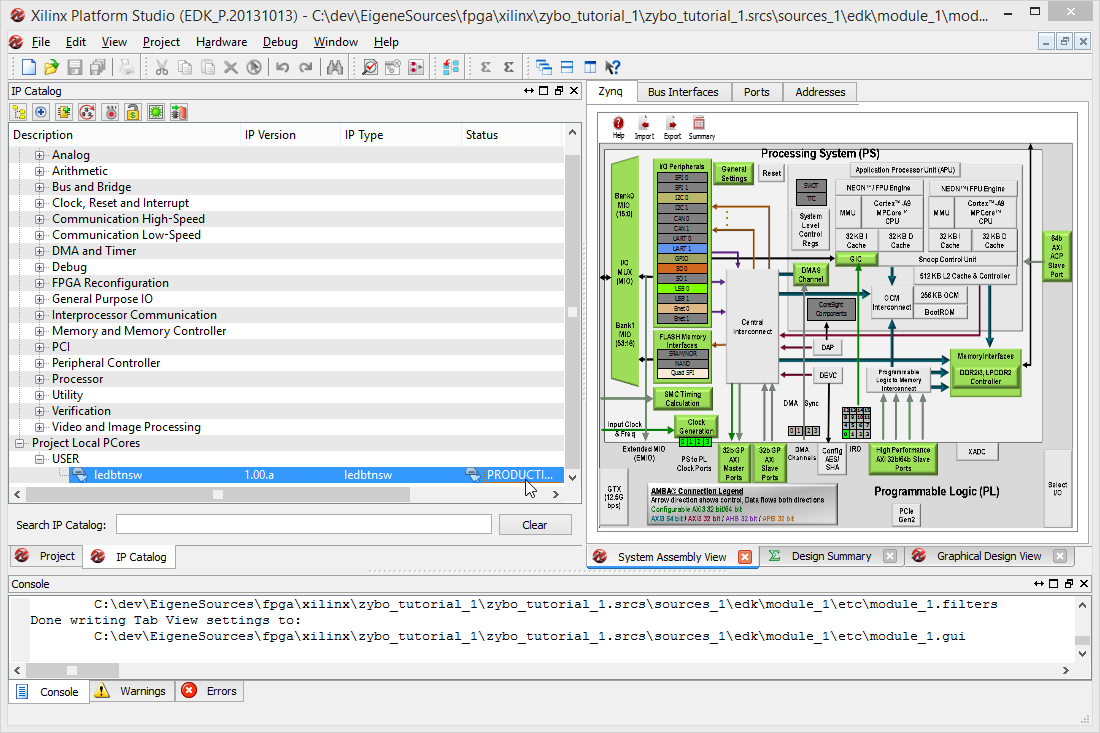
Right-click it in the catalog and select View MPD.
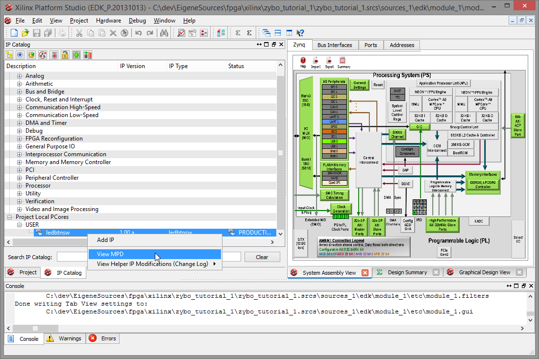
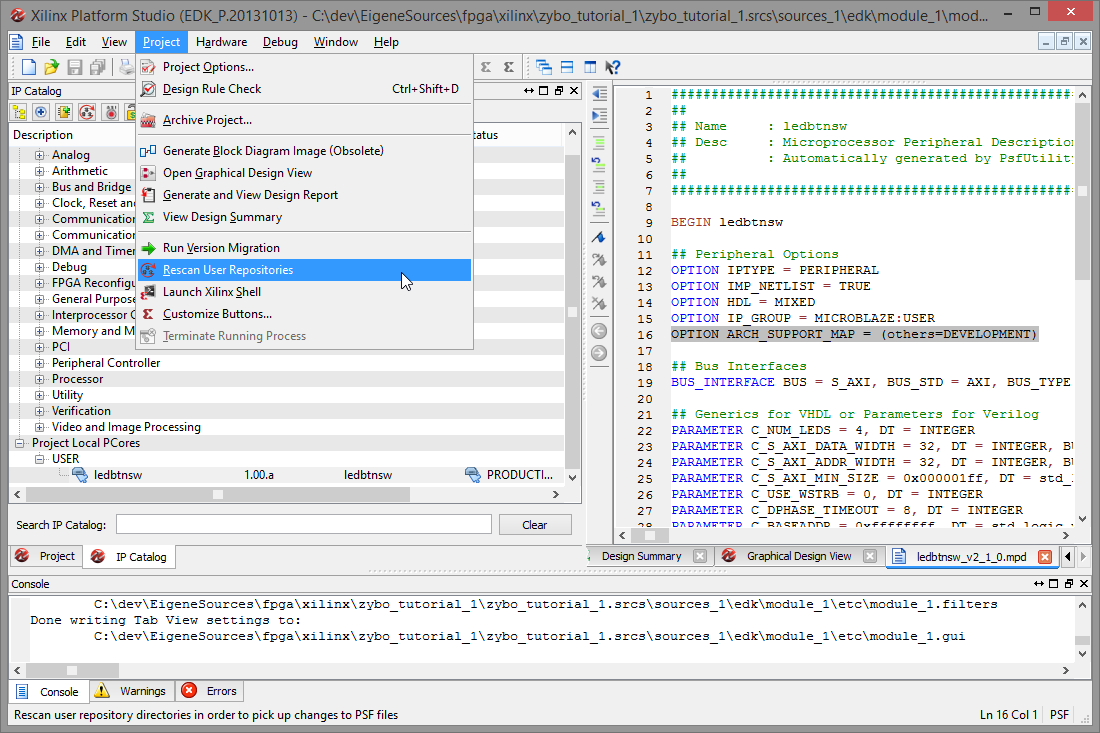
You will notice that the ARCH_SUPPORT_MAP line is missing. In case you didn't write it down, it was:
OPTION ARCH_SUPPORT_MAP = (others=DEVELOPMENT)Re-add it to the file, then select Project, Rescan User Repository to force XPS to re-read it.
You will find that the IP is now marked as DEVELOPMENT.
The import procedure should only be necessary when the public interface of the IP changes, i.e. when changes to the IP wrapper file are made, or if additional files are added.
Configuring the IP ports
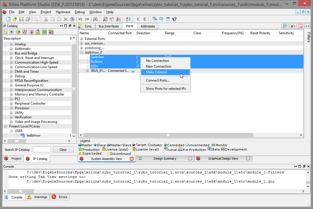
Head to the Ports tab of the System Assembly View. You will see that the re-imported IP now lists the two inputs and one output we defined, and that they are currently unconnected. Note that the Range field matches the number of connections we defined in the generic parameter, C_NUM_LEDS.
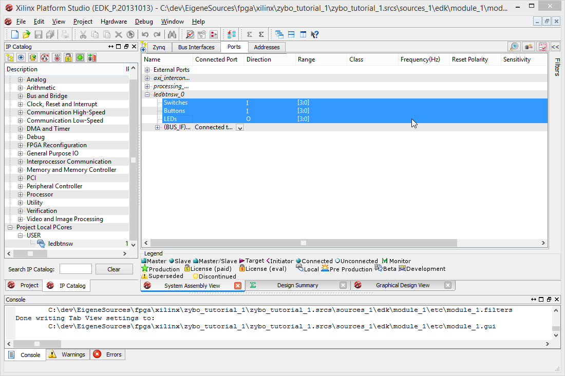
In order to wire these signals to physical pins, we need to convert them to external connections. Right-click the entries and select Make External.
After that, they are listed as External Ports with default names based on the signals names and the IP name.
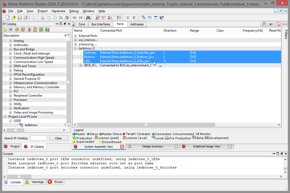
Keep note of these port names (or change them by single-clicking on them) and then close XPS. Doing so will save your changes.
Parts of the tutorial
- Previous: Editing the IP logic.
- Next: Synthesizing and creating the Bitstream.